Typical machined parts
Camera mounts, lighting brackets, base plates, sensor holders, calibration blocks and alignment fixtures.
XHR machines stable and accurate parts for optical inspection systems where alignment, flatness and vibration resistance affect measurement reliability.
Application engineering answer
Optical inspection parts should preserve the mechanical references that control the optical axis, focus distance, lighting position and motion-system alignment. Buyers should mark these functional relationships, define allowable adjustment, and separate critical mounting surfaces from covers or cosmetic geometry so machining and inspection effort is applied where it matters.
| Review area | What buyers should define |
|---|---|
| Application fit | Optical mounts, stage plates, camera and light holders, covers, adapters and alignment hardware. |
| Drawing focus | Identify optical-axis references, stage interfaces, locating features, adjustment travel, cable clearance and protected surfaces. |
| Material and finish | Confirm stiffness, thermal behavior, weight and whether dark, low-reflection, corrosion-resistant or cosmetic finish is needed. |
| Inspection and RFQ | Specify critical distances, hole position, flatness, perpendicularity, fitted features and the intended assembly relationship. |
Technical review: XHR Precision Machining
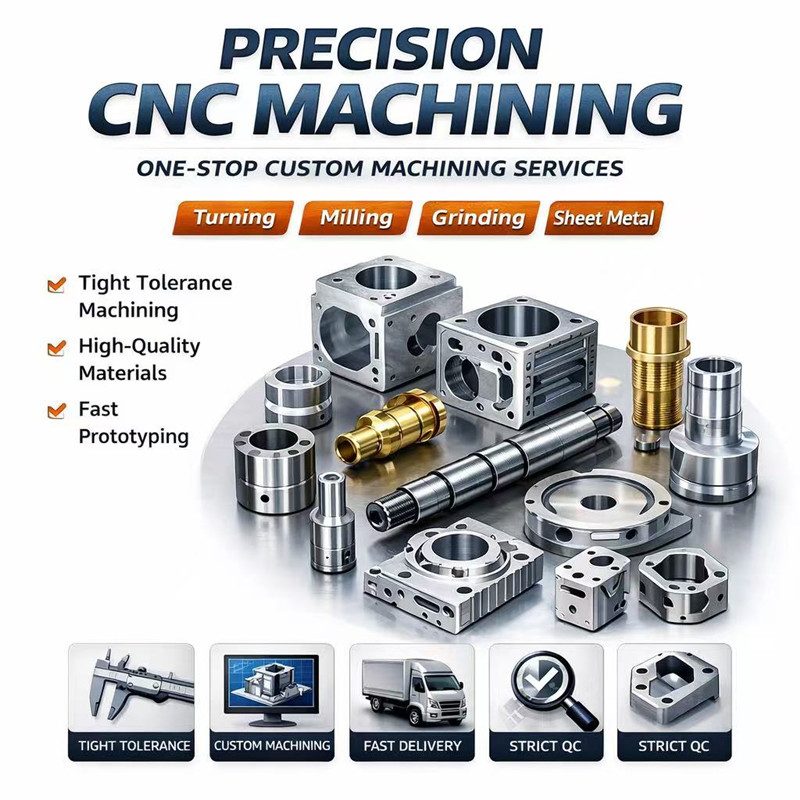
Precision CNC machining for optical inspection equipment parts including camera mounts, light brackets, base plates, sensor holders and alignment fixtures.
Camera mounts, lighting brackets, base plates, sensor holders, calibration blocks and alignment fixtures.
Aluminum is common for lightweight structures, while black anodizing or stainless steel can help with reflection control and stability.
Flatness, perpendicularity, thread quality, hole position and clean surface protection should be specified clearly.
Small position errors can affect camera or sensor calibration. Mark datum surfaces, slots and adjustment ranges clearly.
Yes. Send 2D drawings, 3D files, material, quantity, tolerance notes and surface finish requirements for review.
Yes. XHR supports prototype machining, low-volume orders and repeat batches after the design is validated.
Critical dimensions, inspection method, material grade, surface finish, quantity and target delivery date reduce assumptions.
Optical inspection equipment parts often need accurate mounting surfaces, stable alignment, clean edges and consistent surface finish. XHR can machine camera mounts, sensor brackets, light-source holders, fixture plates, adjustment blocks, covers and precision mechanical parts used in inspection and vision systems.
Mark datum surfaces, hole positions, slot width, flatness, perpendicularity, threaded features and alignment faces that affect optical setup.
Black anodizing, matte finish, polishing, sandblasting or cosmetic requirements should be included before quotation so finish allowance can be reviewed.
Inspection can focus on fit-related dimensions, mounting hole patterns, surface condition and consistency for repeat assemblies.