Typical machined parts
Camera mounts, lens brackets, light frames, sensor plates, inspection bases and adjustable positioning parts.
XHR supports machined parts for machine vision systems where camera alignment, sensor position, stiffness and clean installation surfaces affect inspection accuracy.
Application engineering answer
Stable vision hardware starts with a clear datum chain between the camera, lens, light source, sensor and machine frame. Drawings should distinguish alignment features from general geometry, define adjustment travel and locking points, and identify surfaces where finish, reflectivity, vibration or thermal change can affect imaging.
| Review area | What buyers should define |
|---|---|
| Application fit | Camera plates, lens brackets, light-source supports, sensor mounts, adjustment blocks and inspection-system hardware. |
| Drawing focus | Define optical-axis references, mounting patterns, adjustment slots, locking features, clearances and alignment datums. |
| Material and finish | Balance stiffness and weight, then specify anodizing, black finish, glare control or protected cosmetic surfaces where needed. |
| Inspection and RFQ | Mark alignment-critical dimensions, fitted holes, flatness, perpendicularity, thread requirements and assembly references. |
Technical review: XHR Precision Machining
Precision CNC machining for machine vision components including camera mounts, lens brackets, lighting frames, sensor plates and inspection fixtures.
Camera mounts, lens brackets, light frames, sensor plates, inspection bases and adjustable positioning parts.
Aluminum is common for lightweight frames, while stainless steel or black surface finishes may be used for stability and reflection control.
Hole position, perpendicularity, flatness, thread quality and assembly reference faces should be defined clearly.
For vision hardware, small shifts in camera or sensor position can affect measurement. Mark datum faces and adjustment slots clearly in the drawing.
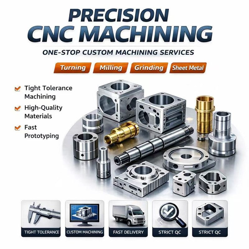
Yes. Send drawings, 3D files, material, quantity, tolerances and finish requirements for review.
Yes. XHR supports prototype machining, small batch orders and repeat production after validation.
Critical dimensions, inspection method, surface finish, material grade, target quantity and delivery requirements help reduce assumptions.
Attach drawings, material, quantity, tolerances and surface finish requirements. XHR will review the machining route and reply with practical feedback.